Declined
Last Updated:
22 Oct 2021 10:29
by Petar
Martin Ivanov
Created on:
04 Oct 2021 11:56
Category:
Diagram
Type:
Bug Report
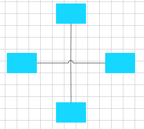
Diagram: Connection bridges are not drawn when appearing over a connection point
If two connections are crossing one another at a connection point, the connection bridge (bow or gap) is not drawn.
This is reproducible only with the ConnecitonBridge property of RadDiagram set to Bow or Gap.
A possible workaround is to create a class that derives from RadDiagramConnection and override its CreateGeometry, where you can manually calculate and create the geometry of the connection line along with a connection bridge geometry.
1 comment
Petar
Posted on:
22 Oct 2021 10:29
By design algorithm runs segment by segment where segment is straight line between 2 points.
Segment could be the whole connection or many parts of it if connection has many intermediate connection points. Segment crossing is considered a point of crossing between 2 segments which is at a minimum distance to the start/end points of both segments. Why ? This is because gap geometry is constructed by the following three parts - from segment start to gap (or bow), from gap start to gap end, and from gap end to segment end.
Another characteristic of the algorithm is that Bow is created in the uppermost connections and Gap is created for the bottom ones.
So in case where two segments cross at their start/end points, basically gap is not created because the algorithm rejects it is crossing because there is no minimal distance to the segment end.
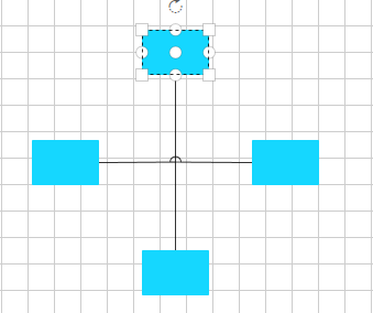
We played a bit with the parameters of the algorithm. Lets say we can introduce a parameter set to 0, meaning that no distance to segment start/end is needed to consider a crossing.
In sample cases where straight connection crosses the intermediate point of other connection this works well:
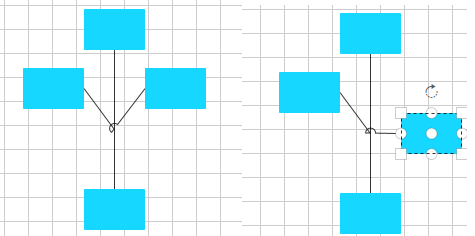
However, imagine the intermediate connection is part of the uppermost connection, or both connection have such points which overlap. This will generally lead to the following:
- bow is needed for left part of the connetion -its end overlaps other connection
- bow is needed for right part of the connection - its start overlaps the other connection
Then algorithm must remove one of the bows or combine their geometries into one. Possible to implement however, it will surely degrade the performance for lots of connections. Here is the moment to say that generally algorithm slow due to its complexity, so every additional logic will make it slower and harder to use .
One last but not least important note is that connections might not generally be orthogonal. Check the following image:
If gap is created in these cases, its size, rotation and geometry should somehow be dependent on the angle the connection segments form, otherwise it looks ugly / glitchy. However, I guess you understand such complex geometry drawing will also eventually slow down the algorithm. This is one of the reasons it runs segment by segment and gap is part of a segment, not part of multiple segments.
This is the reason for declining this item as bug report. It could be reopened as feature request if possible algorithm is found.
Solution: Remove intermediate points which do not make turn in the connection geometry.
Segment could be the whole connection or many parts of it if connection has many intermediate connection points. Segment crossing is considered a point of crossing between 2 segments which is at a minimum distance to the start/end points of both segments. Why ? This is because gap geometry is constructed by the following three parts - from segment start to gap (or bow), from gap start to gap end, and from gap end to segment end.
Another characteristic of the algorithm is that Bow is created in the uppermost connections and Gap is created for the bottom ones.
So in case where two segments cross at their start/end points, basically gap is not created because the algorithm rejects it is crossing because there is no minimal distance to the segment end.
We played a bit with the parameters of the algorithm. Lets say we can introduce a parameter set to 0, meaning that no distance to segment start/end is needed to consider a crossing.
In sample cases where straight connection crosses the intermediate point of other connection this works well:
However, imagine the intermediate connection is part of the uppermost connection, or both connection have such points which overlap. This will generally lead to the following:
- bow is needed for left part of the connetion -its end overlaps other connection
- bow is needed for right part of the connection - its start overlaps the other connection
Then algorithm must remove one of the bows or combine their geometries into one. Possible to implement however, it will surely degrade the performance for lots of connections. Here is the moment to say that generally algorithm slow due to its complexity, so every additional logic will make it slower and harder to use .
One last but not least important note is that connections might not generally be orthogonal. Check the following image:
If gap is created in these cases, its size, rotation and geometry should somehow be dependent on the angle the connection segments form, otherwise it looks ugly / glitchy. However, I guess you understand such complex geometry drawing will also eventually slow down the algorithm. This is one of the reasons it runs segment by segment and gap is part of a segment, not part of multiple segments.
This is the reason for declining this item as bug report. It could be reopened as feature request if possible algorithm is found.
Solution: Remove intermediate points which do not make turn in the connection geometry.
Type
Status
- All
- Completed (3554)
- Declined (790)
- Duplicated (58)
- In Development (10)
- Under Review (1)
- Unplanned (3187)
- Won't Fix (151)
Category
- All
- UI for WPF
- AI Coding Assistant
- AIPrompt
- AutoCompleteBox
- AutoSuggestBox
- Badge
- Barcode
- BarcodeReader
- Book
- BreadCrumb
- BulletGraph
- BusyIndicator
- Buttons
- Calculator
- Calendar
- Callout
- CardView
- Carousel
- ChartView
- ChartView3D
- Chat
- CircularProgressBar
- CloudUpload
- CollectionNavigator
- ColorEditor
- ColorPicker
- ComboBox
- ContextMenu
- Data Virtualization
- DataBar
- DataFilter
- DataForm
- DataPager
- DataServiceDataSource
- DatePicker
- DateRangePicker
- DateTimePicker
- DesktopAlert
- Diagram
- Docking
- DragAndDropManager
- DragDropManager
- EntityFrameworkCoreDataSource
- EntityFrameworkDataSource
- Expander
- ExpressionEditor
- ExpressionParser
- FileDialogs
- FilePathPicker
- GanttView
- Gauge
- GridView
- HeatMap
- HighlightTextBlock
- ImageEditor
- Installer and VS Extensions
- LayoutControl
- Licensing
- ListBox
- Map
- MaskedInput
- Menu
- MultiColumnComboBox
- NavigationView
- NotifyIcon
- NumericUpDown
- OfficeNavigationBar
- OutlookBar
- PanelBar
- PasswordBox
- PDFViewer
- PersistenceFramework
- PipsPager
- PivotGrid
- ProgressBar
- PropertyGrid
- RadialMenu
- Rating
- RibbonView
- RichTextBox
- ScheduleView
- Slider
- SlideView
- Sparkline
- SpellChecker
- SplashScreen
- Spreadsheet
- StepProgressBar
- SvgImage
- SyntaxEditor
- TabbedWindow
- TabControl
- TaskBoard
- TileList
- TileView
- TimeBar
- TimeLine
- TimePicker
- TimeSpanPicker
- ToolBar
- ToolTip
- TouchManager
- TransitionControl
- TreeListView
- TreeMap and PivotMap
- TreeView
- VirtualGrid
- VirtualizingWrapPanel
- VirtualKeyboard
- WatermarkTextBox
- WebCam
- Window
- Wizard